Medical Gas Pipeline System Design Calculation
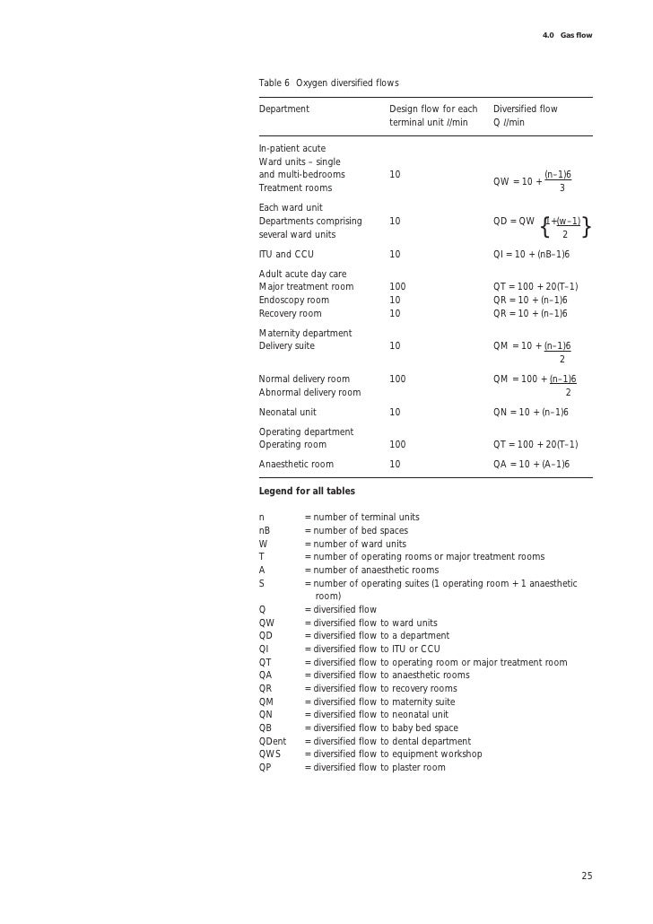
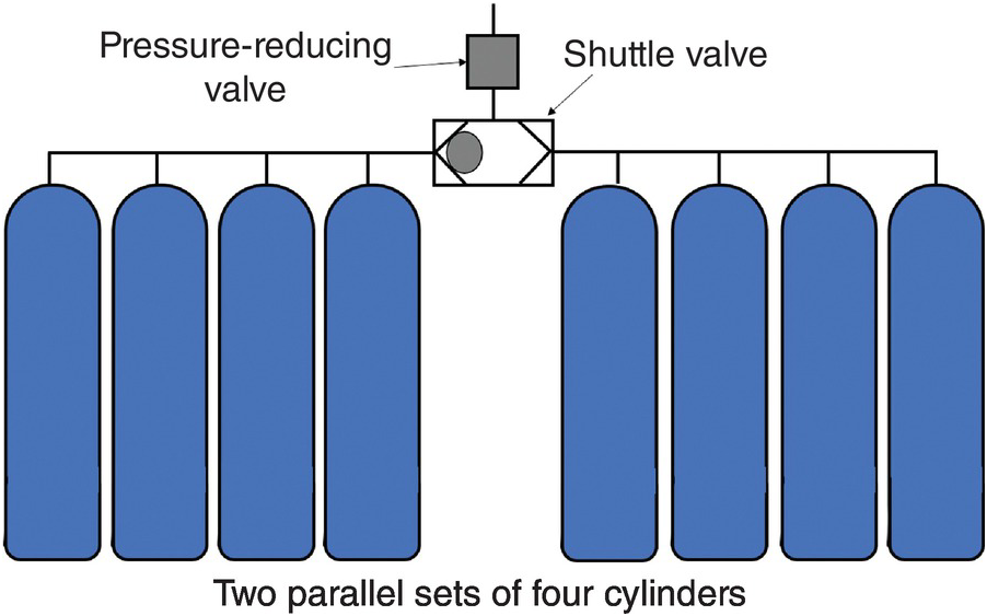
Medical gas pipeline system design calculation. Design installation validation and verification vi at any one time. The typical medical gas manifold for oxygen N 2 O CO 2 or medical AIR commonly consists in accordance with EN ISO 7396-1. Induced pressure drop along the pipeline by a difference of quadratic pressure at the inlet and outlet of the pipeline section.
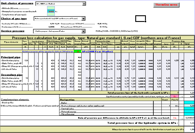
Figure 2 Typical pressure profile along a gas pipeline. Measured length of pipe 1752 m Design flowrate270 Lmin From Tables 2-5 Nearest length of pipe from Table 15 m Diameter 15 mm Pressure drop from Table 7 kPa From equation 2-1 Δp38986 kPa. Comprehensive solutions from one hand.
HTM 2022 Medical gas pipeline systems. 2 2 A x 1 out in e A B p p e Eq. Medical gas pipeline systems Part B.
Nitrogen shall be 160 psi 11 bar to 185 psi 127 bar at maximum flow. All pressure systems except nitrogen shall be 50 psi 34 bar to 55 psi 38 bar at maximum flow. 28 FUEL GAS SERVICE 29 MEDICAL GAS SYSTEMS 291 Systems for Medical Clinics 292 Dental Clinics 293 System Control Valves 294 Alarm Systems 295 Gas System Sources Storage 296 Point-of-Use Sources 297 Alternative Compressed Air Sources 298 Color Coding and Labeling 299 Medical Gas Systems Outlets.
Pass fromc-1 Given as measured. Medical gases HTM 02-01 Medical gas pipeline systems Part A. Health Technical Memorandum 02-01.
Identity of supply This is achieved by ensuring that all points to which the user can connect medical equipment terminal units. Cu Ag 9990 0015 P 0040 Pipes degreased to ensure hydrocarbons on surface. DescriptionETR is supplier and manufacturer of PSA oxygen generator systemmedical oxygen plant oxygen cylinder filling plant high-purity oxygen generator medical central gas supply system medical compressed air system nurse call system which are widely used around the world and try our best to provide best service for our customers.
3 A typical pressure profile calculated from Eq. Medical Gases System Design and Calculation Concept by using Revit as a modeling and Codes as a design.
Medical gas pipeline systems Part B.
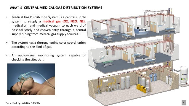
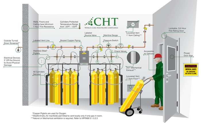
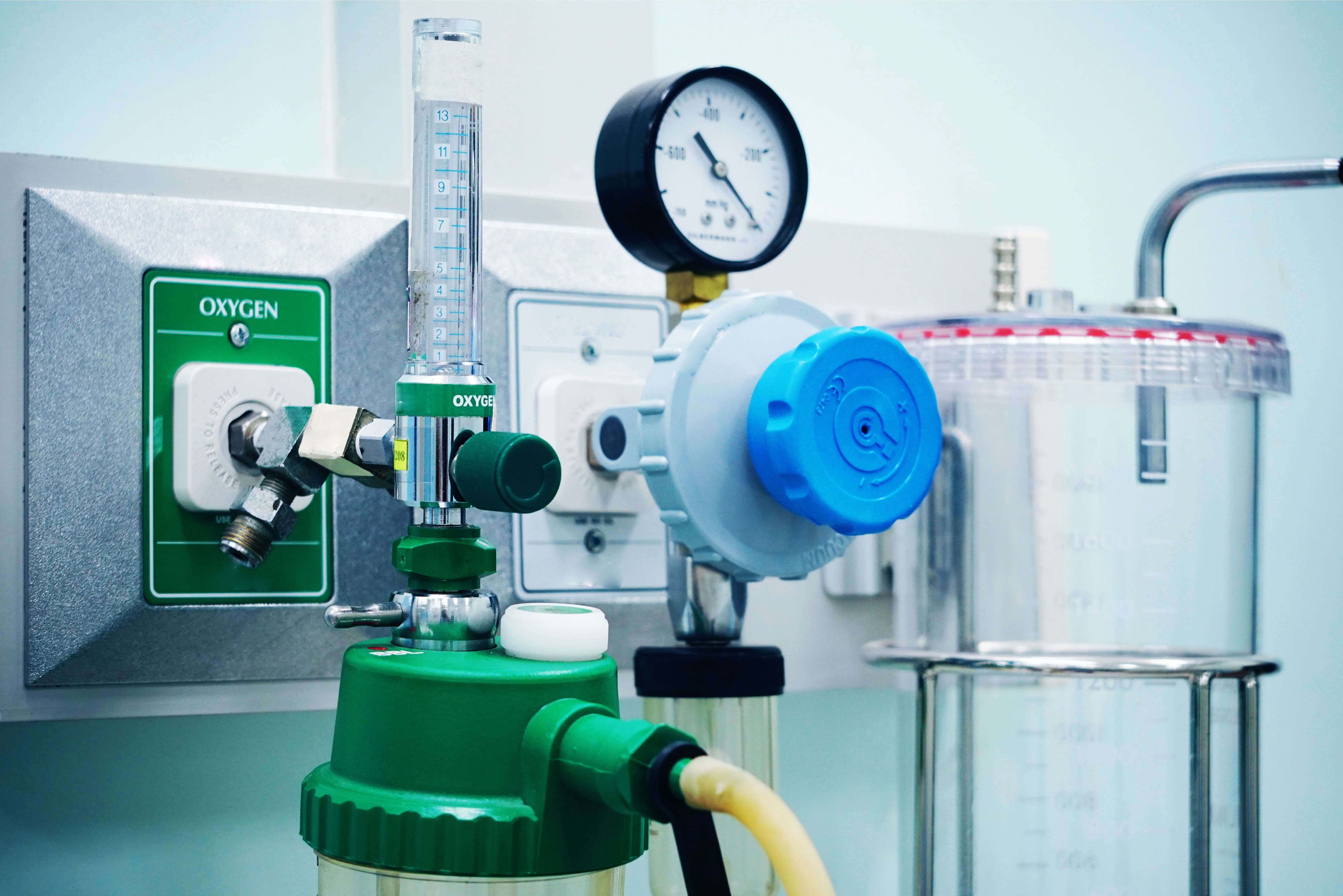
Medical gases HTM 02-01 Medical gas pipeline systems Part A. Nitrogen shall be 160 psi 11 bar to 185 psi 127 bar at maximum flow. Consultation planning project management installation assembly certification commissioning and. Health Technical Memorandum 02-01. Design Medical gases and vacuum systems to deliver the following nominal pressures at the points of use. HTM 2022 Medical gas pipeline systems. Comprehensive solutions from one hand. Design installation validation and verification Created Date. Medical gas manifolds are designed to supply the correct pressure and volume of gas from gas cylinders or tanks to a healthcare facilitys pipeline system.
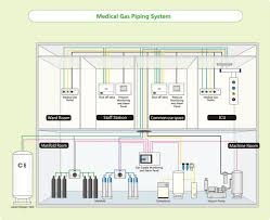
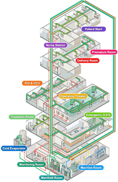
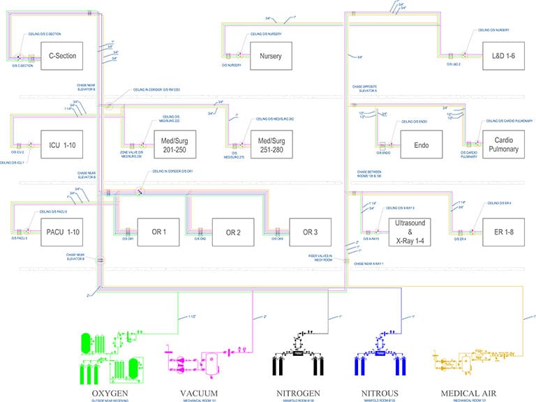
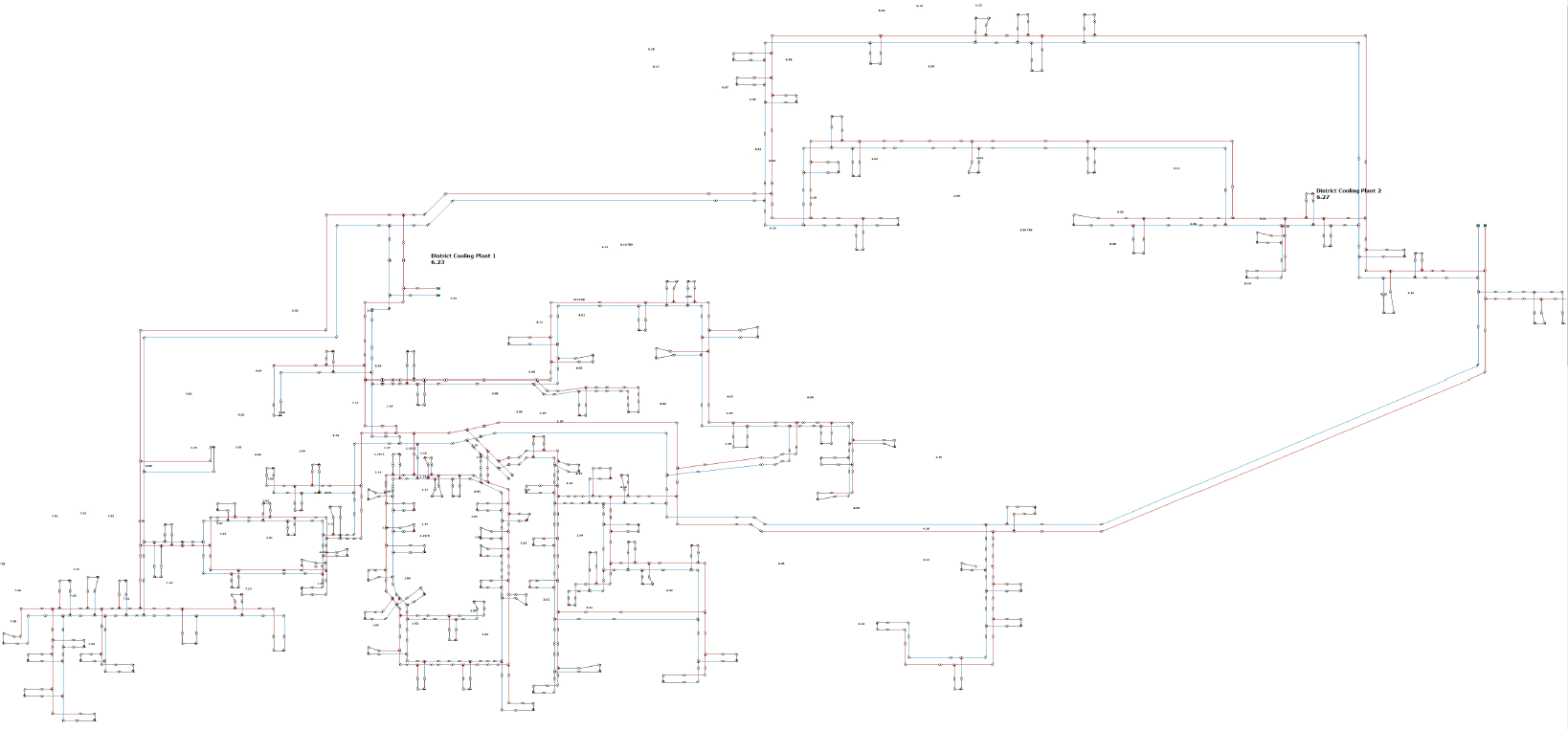
4- 24 shows distribution of mainlines in second floor Example. Consultation planning project management installation assembly certification commissioning and. Comprehensive solutions from one hand. Induced pressure drop along the pipeline by a difference of quadratic pressure at the inlet and outlet of the pipeline section. Figure 2 Typical pressure profile along a gas pipeline. Measured length of pipe 1752 m Design flowrate270 Lmin From Tables 2-5 Nearest length of pipe from Table 15 m Diameter 15 mm Pressure drop from Table 7 kPa From equation 2-1 Δp38986 kPa. A Medical Gas Pipeline System has a complex structure but it must function as if from a single cast.


















Very well explained about Medical gas pipeline system. Thanks for sharing such an useful information. Medical Gas Suppliers in UAE
ReplyDeleteGreat Content!You have explained everything very nicely,thanks for providing quality content.
ReplyDelete